5% off


Keydiy KD MP Dedicated Solder-free Wire Adapter Clip for KD-MP MLB MQB48 Tool
Latest price: €23.06Buy Now: €21.91
5% off
Product: KD MP Dedicated Solder-free Wire Adapter Clip
![[UK/EU Ship] Hot KEYDIY KD MP KD-MP 5-in-1 with KD-MATE, KD-MP MLB/MQB Tool, MLB26 MLB09 MLB08 MLB Keys Promotion Package](/upload/pro-xs/25091017574944166338.jpg)

3 Product: KD MP Dedicated Solder-free Wire Adapter Clip
15th Anniversary Special Offer!
Sept. 30 – Oct. 30
Over 300 GBP Get Free Godiag J2534 (SP421-B)
Over 600 GBP Get Free Vgate vLinker (SP392)
Over 1000 GBP Get Free Godiag GT100 (SO537)
Whatsapp +86 13983755934
Sept. 30 – Oct. 30
Over 300 GBP Get Free Godiag J2534 (SP421-B)
Over 600 GBP Get Free Vgate vLinker (SP392)
Over 1000 GBP Get Free Godiag GT100 (SO537)
Whatsapp +86 13983755934
Shipping:
Free Shipping
Standard Flat Rate Shipping ServiceEstimated delivery time: 7-15 working days.See details »
Returns:
Return for refund within 30 days,buyer pays return shipping. Read details »
€21.91
In Stock.
Free Shipping
Product Description
This is the Keydiy KD MP dedicated solderless wire adapter clip for the KD-MP MLB MQB48 tool.
Keydiy KD MP Dedicated Solder-free Wire Adapter Clip
Product Description:
This is the Keydiy MP dedicated solderless wire adapter clip for the KD-MP MLB MQB48 tool.


Solder point wiring diagram:

Product Package includes:
1pc x KEYDIY MP Dedicated Solder-free Wire Adapter Clip


Hot Branded Products:










Shipping method and delivery time:
UK Shipping (No Tax) : 2-4 working days arrive. For products marked " UK Ship " and UK local customer
EU shipping (No Tax) : 5-7 working days arrive. For products marked " EU Ship " and from EU countries, if not belong to EU, need to clearance
Yodel (No Tax) : 5-7 days arrive . For products UK out of stock, and customers from UK
Yun Express ( No Tax) : 5 - 9 working days to UK, 7-14 days to other European Countries.
Yanwen (No Tax) : 5 - 9 working days to UK, 7-14 days to other European Countries, ship to all over the world, mainly for UK/EU warehouse no stock
DHL: need to clearance, 3-5 working days arrive. Used for UK/EU no stock, customers request ship this way. Need to clearance, we will declare a low price on the invoice help to clearance.
If you have any questions about the device, the price, or the payment, please feel free to contact us.
Contact Person: Elyza
Whatsapp: +86 13983755934
Telephone: +86 13983755934
Wechat: +86 13983755934
Official Email: Sales@obd2shop.co.uk

Video
How to use the Keydiy KD-MP specific soldering-free clip
Tech Support
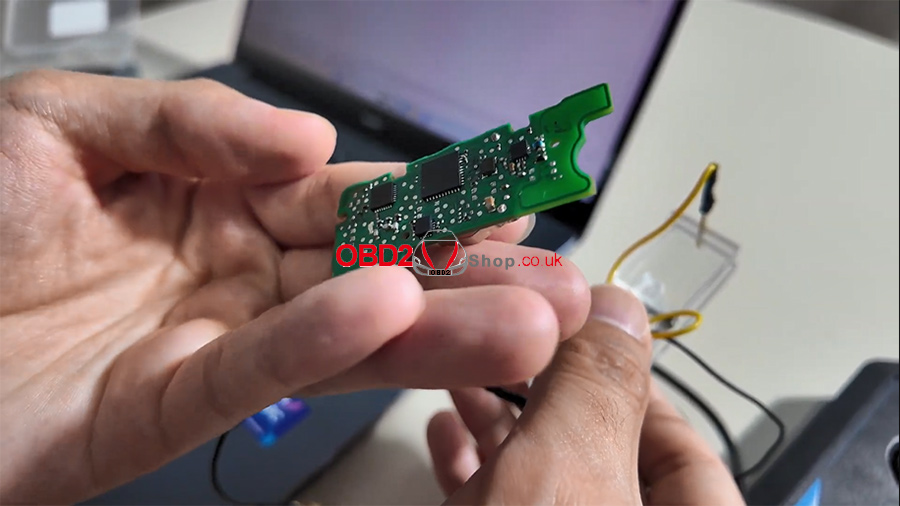
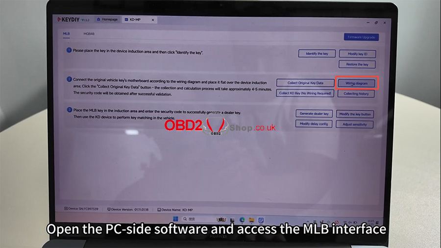
The Keydiy KD-MP soldering-free clip provides a fast and convenient way to read PCB data. This guide walks you through the complete operation process using a Touareg PCB as an example.Step 1: Open PC Software & Locate the Wiring Diagram
Open the Keydiy PC-side software and enter the MLB interface.
Click [Wiring diagram] and locate the diagram corresponding to the Touareg PCB.
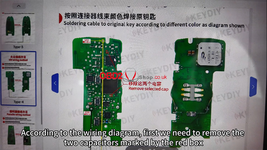
According to the wiring diagram:
Remove the two capacitors marked in the red box.
Position the clip on the points indicated by the yellow circle and black circle.
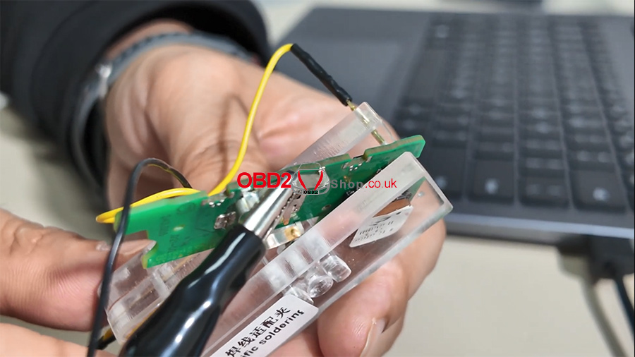
Step 2: Attach the Clip Correctly
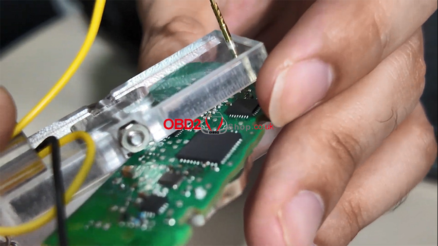
Follow the diagram to attach the clip:
Clip the VCC pin of the soldering-free clip to the VCC location on the PCB.
Clip the black lead to the GND position.
Insert the clip’s wiring harness into the KD-MP device.
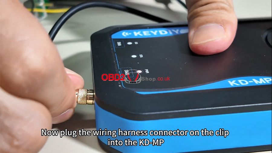
Step 3: Place the PCB for Induction Reading
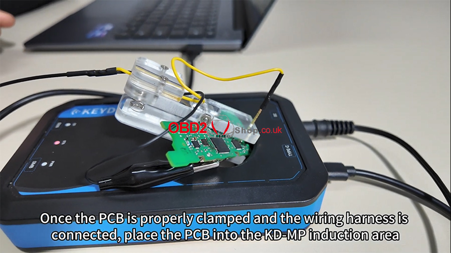
Once the PCB is clamped and the harness is connected:
Place the PCB inside the KD-MP induction area.
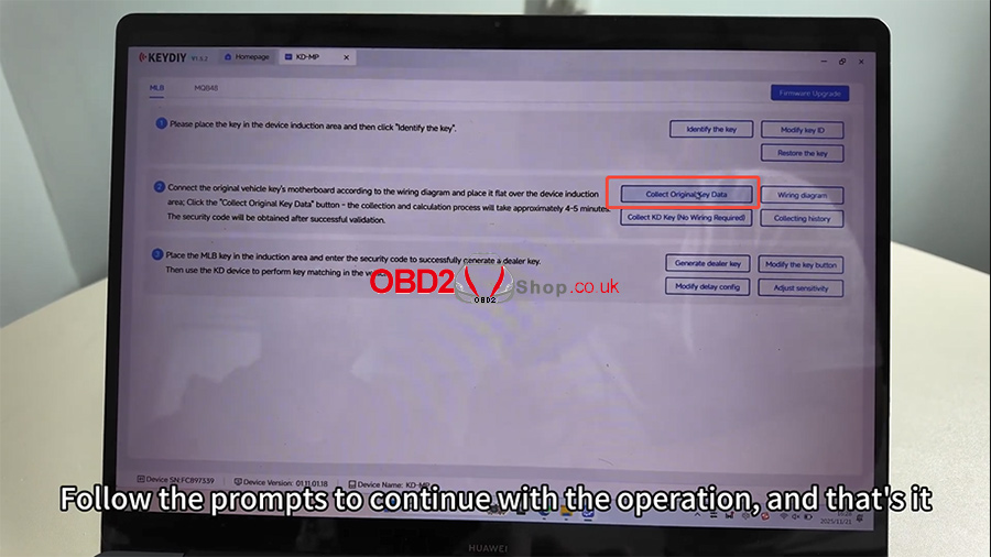
Close the image window on the software interface.
Click [Collect Original Key Data] and follow the on-screen prompts to complete the process.
For a full visual walkthrough, please check the video tutorial below:
https://youtu.be/zZFOFFLGDvg
For more tools and technical support, visit:
www.obd2shop.co.uk
Tags: keydiy key programmer